Evolution of LayupRITE – III – AR Methods

As previously discussed, projector-based AR is promising display method for LayupRITE. However, there are still some downsides. In this post, we will discuss other possible AR and interactivity methods which were tested as part of the various LayupRITE projects. At the end of the post, we will put forward the chosen AR method to be taken further into LayupRITE101, the next iteration of this project.

Head-Mounted Displays – Microsoft HoloLens

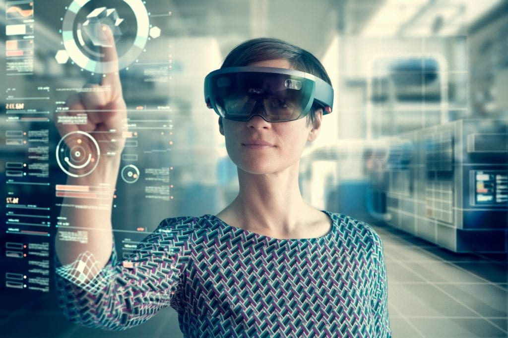
Head-mounted displays are always going to be an attractive option for augmented reality. Directly overlaying digital information onto the user’s field-of-view (FOV) doesn’t require any additional mapping to meet the user perspective and leaves the users hands free. The HoloLens adds to this by also including depth mapping in its projected “holograms” as well as hand tracking and voice commands for control/interaction. What depth mapping allows is for digital assets to be partially (or fully) “occluded” or hidden behind real-world, physical objects.

Image showing a woman using the Microsoft HoloLens
The Microsoft HoloLens

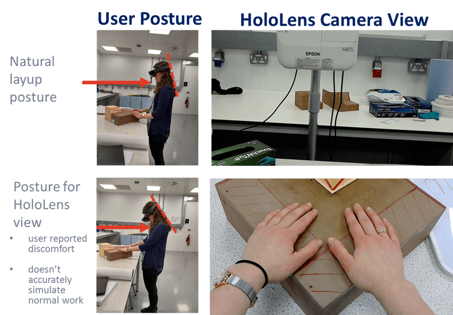
For LayupRITE, this depth mapping could be used to hide portions of the virtual net which would be on the far side of the tool from users, better mimicking the real-world scenario. The HoloLens, on paper, showed real promise for LayupRITE unfortunately practical and ergonomic concerns made it unsuitable. Hand layup of composite plies is close-in work, all occurring within arms-length. Additionally, materials are usually draped onto tools on tables in front of the operator. These two factors combined mean that the vast majority of manual layup work occurs close-in and below the user’s eyeline. To see the holograms presented by the HoloLens’ FOV the user must tilt their head down to uncomfortable angles. This poor posture coupled with the additional weight of the headset made the HoloLens totally unsuitable from an ergonomic perspective.

Image showing the uncomfortable postures required to use the HoloLens in the composite layup environment

Some of these drawbacks, namely the FOV issues and weight distribution, have been addressed by the newer version of the HoloLens, the HoloLens 2. However, it is unclear if the updated hardware will markedly improve on the ergonomic situation. Without being able to test a variety of HMDs, it doesn’t appear they are a viable solution at the moment, although there are some promising-looking devices.

Tablet/Device – Based AR

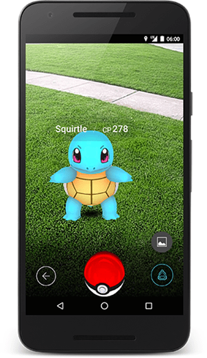
Holding a device with a screen and a rear-facing camera to put virtual/digital content over an image of the real-world is easily the most common AR method. From games such as Pokémon GO to IKEA’s Place AR app for iOS. Most of these applications lie in either the gaming or the advertisement space, but there are also industrial AR apps for assembly and manufacture.

Mobile phone showing Pokémon GO

A device with a screen and rear-facing camera allows the user to point the camera at an object, target, or space, this displays a live feed from the camera onto the screen. The application then recognises the space/target/object and displays digital content. This content can come in two forms, a 2D overlay like a HUD or scaled and oriented 3D content. The level of interactivity is mixed, either for display or information or interacting with the digital content via the screen/device, rather than interacting with it in the real-world space.

What does this mean for LayupRITE?

There are a variety of available display methods for LayupRITE. Projected Interactive Augmented Reality (PIAR), the method used in previous phases of LayupRITE development has a lot of benefits and is probably, when fully realised, the ideal method for display and interaction on the tool/part-in-progress. However, in its current state, particularly the complicated setup and calibration routine, it isn’t as slick or suitable as it needs to be. There have also been concerns raised about cost per system/user.

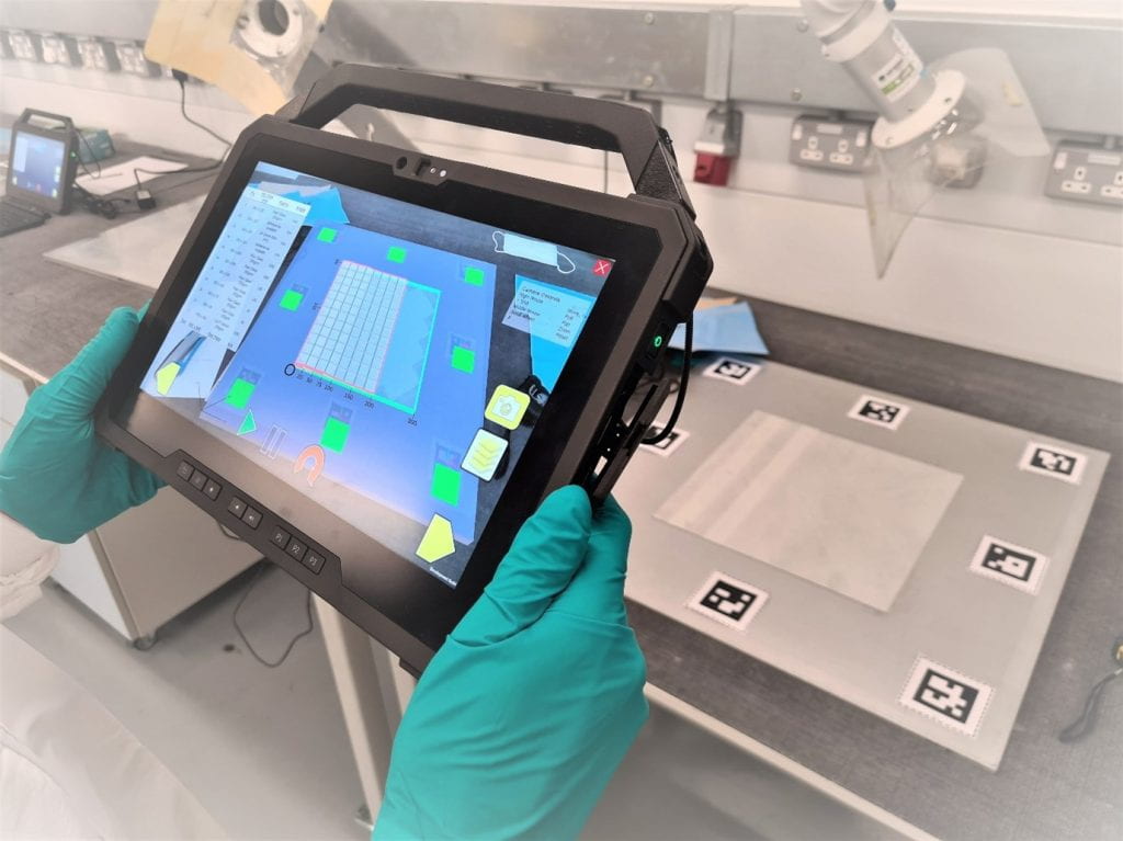
For LayupRITE101, we have moved to a device-based AR method. This currently runs on a Windows 10 tablet device with a rear-facing camera. The camera tracks ARUco markers fixed to the tool, in a similar method to the tool tracking from project 1. Using this method will remove the cost of the Kinect™ and projector, resulting in lower cost and setup at the cost of interactivity. What this will allow us to do is take a tablet and use it for both the classroom stuff and the AR lessons in the workshop. As always, the AR method will likely need refining and developing before it’s truly product
ready.

Picture of LayupRITE being used on a tablet PC during trials at the National Composite Centre
LayupRITE being used on a tablet PC for AR during testing

Lastly, it’s important to point out the utility of developing the drape model to work within a game engine such as Unity. The development environment lets us use prefabs to target display types (PIAR, tablet-AR, VR etc.) so we can build the software modules for multiple display types. So, whilst we’re using tablet-based AR for now, there’s nothing stopping us from developing a VR version or deploying the new and updated software onto a PIAR system in the future.

Outcomes of Ufi Project 1 – System Development

This series of posts is intended to showcase the top-level outcomes of Ufi Project 1 titled “Augmented Learning for High Dexterity Manufacture”. This project was funded by Ufi, a vocational learning charity. In this post we’ll be taking a look at how the whole system developed from it’s previous iterations. As mentioned in an earlier post there were two prior phases of what would eventually turn into the LayupRITE PIAR system.

From Left to Right: KAIL, pre-LayupRITE hardware, LayupRITE PIAR

The first stage was an early proof-of-concept of projecting interactive instructions onto the tool. The second stage was taking that concept and revising the individual elements, improving the projector, and using a newer version of Microsoft Kinect. The Ufi project allowed us to take these components and investigate ways of displaying/mounting them to produce what would become the LayupRITE PIAR system.

Physical Setup

In the left-hand image above, KAIL, the mounting solution was fairly ad-hoc, due to the short-term nature of the research project. The main downside being mounting the standard projector far away enough from the tool for the image to project over it. This necessitated the large fixturing stand shown in the above image which required sandbags to ensure it didn’t topple over, not an ideal setup for the longer-term.

The centre image is from a follow-on project intended to improve and “modernise” the KAIL system. The first difference is in using the updated version of the Kinect. The newer Kinect had a wider field of view and higher resolution depth and RGB cameras, as well as still being supported by Microsoft at the time. The other difference was that a higher-power, ultra-short throw projector was used in place of the standard long-throw version. This project was bright enough to show visible images on carbon fibre in normal clean room lighting conditions.

KAIL (L) Was only visible on glass fibre materials with the lights off. LayupRITE (R) was still visible even on carbon materials under normal clean room lighting

What was noted at this stage was that due to the short throw of the projector, steeper surfaces on parts would be in shadow. This meant that the projector had to be mounted further away from the tool, requiring new fixturing. The new mounting solution gave us the opportunity to mount other equipment, such as the PC and monitor to the pole along with the Kinect. This solution lowered the overall footprint and trailing cables and gave us the form factor for the LayupRITE PIAR system.

Software Setup

Most of the changes from KAIL to LayupRITE PIAR were in software. The previous iterations used the Windows Presentation Foundation (WPF) framework with C♯ as the scripting language. This limited the program to being 2D as the WPF is intended to make desktop apps on screens. The outlines of the instruction target sections were transformed manually by-eye to make the 2D lines conform to the tool. This meant that the software, as written at the start of the project would not work for a general case and needed changing.

Instruction targets in 2D plan view (L) transformed to match contours of tool manually (R)

What was required was a 3D environment that could better handle the collision detection and was compatible with the Kinect. For this we turned to the Unity game engine. Colleagues had had some experience of using Unity with the Kinect and VR in a related project to LayupRITE, so we felt we had enough of a basis to begin using it.

Moving to Unity

An enabling feature of the Unity platform is the “prefab”. Prefabs are building blocks of objects, scripts and other components which can be dropped into a “scene”, or program. These can then be updated in every scene or used as instances. What this means for this program is that we can drop in controls, virtual net objects, etc. This modularity can also enable us to swap out, for instance, the game “camera”, for PIAR this can be swapped to a projector-camera prefab, for another application it could be the HoloLens, or a VR headset. The ability to be modular was a major selling point for Unity for this project.

The virtual nets have warp fibres (purple) woven with weft fibres (orange) with the crossing points (nodes) represented by white circles

What Unity also allowed us to do was to make the hands tracked by the Kinect collide with the in-game representations of the composite net. The representations took the form of spheres (called “nodes” in the model) which represent the crossing points of fibres in a woven fabric. By tracking the interaction with these nodes, we can test and identify which areas of the tool have been interacted with by the user. This means that, through projection information on where to interact and when, we can guide the laminator into working in an optimal, or at least repeatable fashion.

The process for moving from the modelling environment to the projector environment followed a similar process to that of KAIL, but more streamlined:

  1. Simulate the drape of the ply
  2. Identify areas to work in and sequence (this is done by an experienced laminator)
  3. Select the nodes which represent those areas
  4. Project onto the part

Due to the 3D nature and calibrated camera-projector system no “nudging” of individual areas is required. All the above steps can be done in software, although there is still scope for streamlining and automating the steps.

Calibration and Tool Tracking

Calibration of this type (camera, projector stereo calibration) is large topic by itself, so here I’ll just mention that we were using the RoomAlive Toolkit for Unity. This is here the equivalent of KAIL’s “nudging” of the projected output came into play. Whilst the calibration was able to somewhat determine the intrinsic properties of the Kinect camera and the projector, its approximation of their relative positions and angles often required manual tweaking. This is most likely due to the relative angles of the Kinect and projector. A secondary parameter could also have been the ultra-short throw of the projector. Further work would be required to improve the overall quality of the calibration and make the process more streamlined.

A secondary feature which was implemented with limited success was in tracking the tool blocks. This meant that the tool could be moved or rotated, depending on either the user’s preference or to see projection data in shadowed areas. The OpenCV framework for Unity allowed us to use markers fixed to the tool to track its pose and location. The main issue with this was that it was difficult to determine if issues were caused by the tracking, the markers or the calibration.

Recording and Control

A goal of KAIL and this project was also to record and store what the laminator was doing, not just display instructions. To that end, since a camera was pointed at the laminator for the interactive functions, we could also record the laminators’ actions. Naturally, this recording process would be in the control of the operator. This recording of actions could in future be related to some capture of the ply outcomes and those to quality outcomes, from completed part ultrasonic scans. This data would enable us to construct a full model of how touch-level interactions can eventually lead to quality issues.

Screenshot of capture for LayupRITE PIAR showing the skeleton tracking, projected user interface and ARUco tracking markers on the tool

Controls were also to be provided by touch interaction. In a similar was to KAIL there were forward and back buttons to move through the layup stages. Additionally, there were buttons to control the recording, the image above shows the “pause” button on the right-hand side. These where projected buttons which were located on the table.

Second Screen

Another improvement from previous projects was the incorporation of a second screen. Since the application is run on a PC, adding another display (as well as the projector) was simple enough. Thus, the PC’s monitor was used to display additional information to the user. For this project it was intended more as a back-up to the projected info, but it also has the opportunity for displaying information such as where the part-in-progress will be going in a larger assembly/product. This line-of-sight to the final product is potentially a useful and important motivation factor.

Version of LayupRITE PIAR at end of Ufi Project 1

Evolution of LayupRITE – II – PIAR

In the next few posts we will be discussing some of the hardware choices going from the LayupRITE systems on display at CAMX 2018 and Advanced Engineering 2018 to the version undergoing site trials in 2020/2021. In later series of posts we will be discussing the various software upgrades, updates and changes.

LayupRITE at CAMX
The LayupRITE stand in the awards pavilion at CAMX

LayupRITE Projected Interactive AR

The projected AR concept of LayupRITE was a development from earlier UoB research on finding improved and novel ways to display information to a laminator on a part-in-progress. The chosen method was using a projector to overlay information onto a part, a type of augmented reality. To make the system interactive it was coupled with a Microsoft Kinect. The Kinect uses both RGB and Depth cameras to track users as “skeletons”. These skeletons can be used to control the virtual projected instructions. The Kinect was also used to calibrate the projector system to align the projected information to the physical surface.

LayupRITE Alignment Image
Aligning virtual mesh to physical tool

This projected AR experience worked well for the most part. There were some issues with the calibration and alignment not being totally perfect and requiring an oftentimes lengthy setup. However, being able to physically interact with the part and projection data without requiring markers was a definite advantage. It was felt that, with some further development and possibly substituting some components the projected interactive augmented reality (PIAR) system would be an ideal platform for composites layup.

However, with the system as-was at the end of 2019 there were some drawbacks which would need to be addressed. First among which were the setup requirements, both in terms of software and hardware. On the software side, we’ve previously mentioned some of the calibration and alignment issues. The main issue was that the alignment still required manual intervention. Tool tracking was also a planned feature for further development. On the hardware side the 0.2 version required a heavy-duty tank trap and pole-mount setup, which was cumbersome to transport and setup. That said, a solution could easily be designed for a permanent, dedicated workspace.

Image shows pole and clamp mounting of projector, camera, monitor and PC
Rear view of PIAR setup

A second issue was that the interactivity got a lukewarm reception. As mentioned earlier, some substitution would have been required in the future anyway which would be an improvement on the Kinect v2. The third issue was the cost. For the key sector of colleges the cost of the PIAR system was prohibitive for a single-user workstation. This could be mitigated by using a single system with multiple tools and users.

Projected Interactive Augmented Reality (PIAR) LayupRITE System

Pros Cons
Interactive Too expensive for key customer (without modification)
Visible to everyone (unlike head-mounted displays (HMDs)) Calibration and alignment issues
Commercial-off-the-shelf components Some interactivity issues
Runs off regular PC Kinect v2 requires substitution
Cheaper than Laser Ply Projection (LPP) Not a light-weight, transportable system

All in all, the PIAR system remains a viable option for LayupRITE. There are still refinements to be made, particularly in the calibration area, but it is felt that this type of AR is probably the optimal method for layup, both training and practice (until we get Expanse-style holograms, of course!)

Evolution of LayupRITE

The LayupRITE system has seen several iterations over the various projects where it, and its predecessor Kinect Assisted Intelligent Layup (KAIL)[1]. All versions included three basic components: a projector, a Kinect and a PC to run both. The main difference between KAIL and the original version of LayupRITE was essentially a big hardware upgrade.

KAIL had shown the utility in marrying user tracking and projection to instruct composites layup, but the projector wasn’t bright enough to be used on carbon fibre materials in the expected lighting conditions of a clean room. A brief study was carried out to determine the power of projector required for this, with woven carbon fibre prepreg being the worst-case in terms of projection. Unfortunately, the worst-case is also the most likely use-case for the system.

In addition to a power boost an ultra-short-throw (UST) projector was used to try and mitigate some of the mounting issues with standard projectors. These projectors had to be mounted at a longer distance from the workspace and directly overhead, leading to a more complex gantry-style mounting solution. By using a brighter, UST projector we were able to get around many of the projection issues with the older KAIL setup.

Lower-powered projection image
Lowered light levels required by the KAIL system


KAIL Setup
The Kinect Assisted Intelligent Layup (KAIL) setup
LayupRITE_v0 setup
An early image of the LayupRITE setup

[1] M. Such, C. Ward, W. Hutabarat and A. Tiwari, “Intelligent Composite Layup by the Application of Low Cost Tracking and Projection Technologies,” Procedia CIRP, vol. 25, pp. 122-131, 2014.