Outcomes of LayupRITE101

Toward the end of 2019 LayupRITE started its follow-on Ufi funded project. The main aims of this project, titled “LayupRITE101: Augmented Training for Composites”, was intended to integrate the LayupRITE system into a more complete training course. For this project, LayupRITE would be used to augment the teaching of the NCC’s “Introduction to Manual Prepreg Layup” course. This 2-day course gives both theoretical and hands-on instruction in the manufacture of prepreg components by manual layup. This includes safety, storage, materials, tooling, layup, consolidation, and finishing operations. Along with an e-learning component designed to enhance the current classroom-based course notes, LayupRITE simulations would be used to demonstrate theory points and guide the workshop tasks.

Feedback from Ufi Project 1

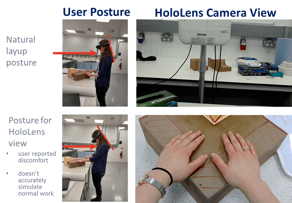
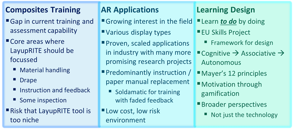
The first Ufi-funded project gave the LayupRITE developers a lot of useful feedback and learning points. Some of the points related to “what good looks like” for augmented reality backed learning, others related to cost and form-factor concerns.

In terms of “what good looks like” that was missing from the first project, the key element was in being able to make mistakes for practice. The drape algorithm solved the drape for the entire net, meaning that the user could only really change the start point. This was still useful as the start point in a layup generally determines the final ply outline and was taken as a learning accelerator. Project 1 also demonstrated that, without guidance, people will use a variety of starting locations.

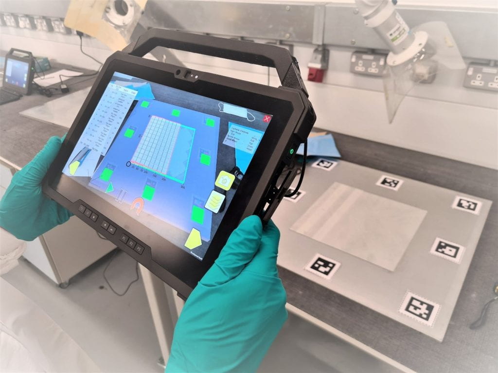
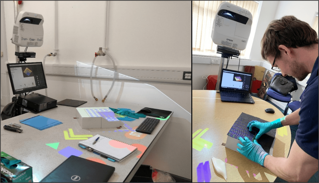
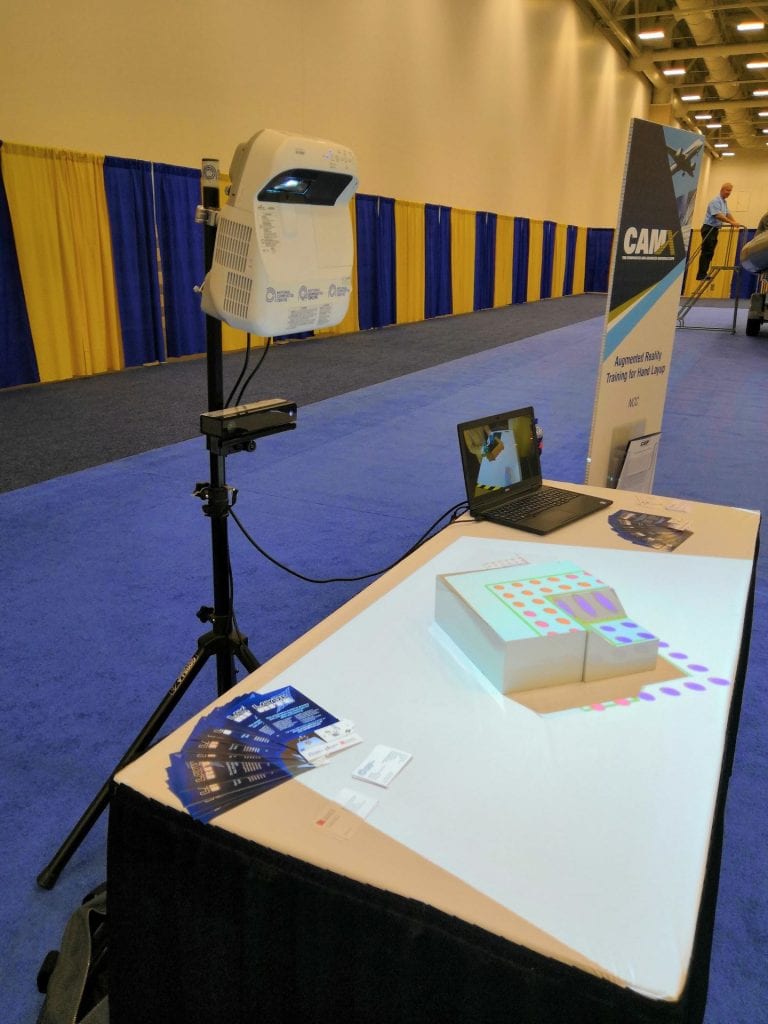
Feedback from our target customers, further education institutes, was that the projector-based system would either be too costly or too bulky for the environments they would use it in. Additionally, during development there were issues with setup time and calibration, as well calibrating between setups. As a result of these concerns, the form-factor and AR delivery for LayupRITE101 was chosen as tablet-based, pass-through AR. The intention from the developer was that the same computer could be used in both the classroom and the workshop to guide the exercise.

LayupRITE101 Drape Simulation

“Facilitating deliberate practice”

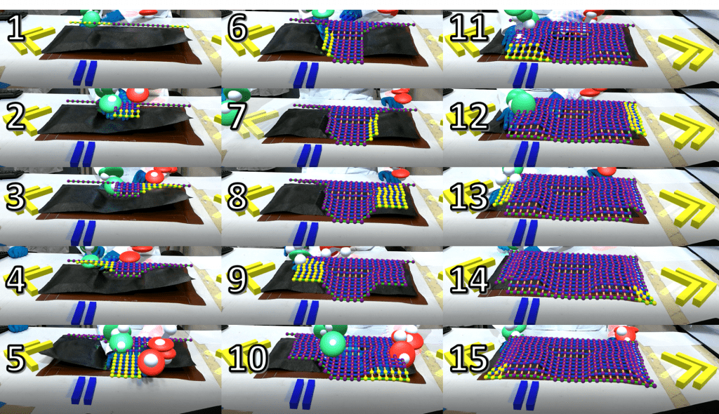
The Pin-Jointed Net method for a kinematic drape solves the drape for the entire net and reports back the resulting net shape and shear angle. Previous work [1] has shown that drape simulation doesn’t necessarily match the feature-by-feature approach employed by laminators. Additionally, whilst it quickly solves the drape of a virtual net with next to no initial input, save for a start point in our case, it doesn’t allow the user to introduce (deliberately or otherwise) defects. The method also lacks the interactivity which benefits learning.

The pin-jointed net assumption does lend itself to quickly trialling start points. Start point is a key accelerator in learning how composite plies drape. As such, it was made into its standalone lesson “module”. The 4 lesson modules developed for the course will be discussed later.

What was useful for this project was the development of a simulation that could show how the net should deform in real time. What would be even more beneficial would be a net that could be interacted with, so a user could practice draping a virtual net. This virtual net would differ from the automatically solving net in that the user would be able to interact with it and attempt to drape it in the more natural feature-by-feature style. This would require creating a new type of manually controlled virtual net in the Unity environment.

What this manual net gave us was a net where nodes could be fixed in space or moved. What this enabled was in pre-shaping or folding the virtual net prior to placing it on the tool.


By fixing some nodes and moving others the net was also able to demonstrate another key learning point for composite drape: bias-extension shear. Fibres are strong, that’s the point, so pulling in the fibre direction won’t allow you to deform, shear and shape the net. Pulling in the direction off the fibre axis (the “bias” direction) is how a laminator can shear the net to make it conform to the mould tool. This was also a key learning accelerator and was made into its own module.

Drape Simulation Modules

In total 4 modules were developed and trialled within LayupRITE101In addition to the two accelerators mentioned earlier, start point and bias extension, there was a “free practice” module and the workshop exercise.

Bias-Extension and Shear

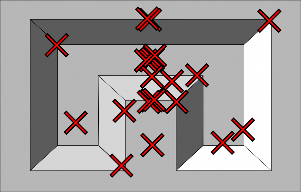
The bias-extension less is a quick (under 5 minute) exercise to demonstrate the learning accelerator of the same name. The final version is compatible with both mouse and touch controls and shows the shear increasing by the net changing colour and eventually displaying an “X”-shaped symbol when the cell is over-sheared. The exercise demonstrates pulling the edges and corners on both 0°/90° and ±45° nets.

Start Point

This exercise uses the automatically draping nets to compare starting points. The user uses the mouse or touch to select the starting node and tap/click to begin the drape. There is a text readout of some net statistics (net fibre angle, max shear, average shear, % over-shear) which compares the last two nets positioned. Additionally, the graphic will show the outlines of both nets and the full shear mesh of the topmost net.
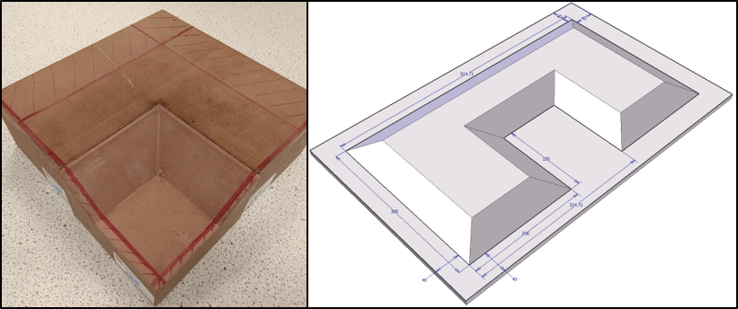
Workshop Exercise

This module uses script controlled manual nets to give step-by-step instructions for the workshop exercise. This includes ply order, orientation, location, location of any joints/overlaps, material type, and cores/adhesives etc. The module also has an exploded view for easy visualisation and is intended to effectively replace the paper ply book and work instruction. The module also included an AR function where the virtual plies would line up relative to printed AR markers positioned on the tool. Feedback from users was very positive about the “virtual ply book” aspect of the module and less positive about the AR aspects/implementation. However, this module gave confidence in the whole system and possible expansion routes for LayupRITE.

VFP Basic – Free Practice

Unlike the other modules, VFP Basic doesn’t have specific guidance and is intended as a practice area for users. Tools (in *.stl format) could be loaded in and automatically sized nets in any fibre orientation could be created. This includes both automatically and manually draped nets and their shear meshes would be displayed visually in the program. Nodes can be fixed in space, selected, and moved or left as “normal” with their movement/position to be solved by the simulation. When a node contacts the tool surface it sticks and becomes “draped”. To lift the stuck node off the tool there is an “undo” tool. This is typically more challenging in the real world, but it allows users to make and fix mistakes, important for learning.

Trials

There were two sets of in-person trials planned, at the National Composites Centre and with partner further education institutions. Unfortunately, due to the global Coronavirus pandemic, these plans were severely curtailed. The NCC trials were still able to go ahead with masks and physical distancing, but the offsite trials had to be made virtual. This necessitated some additional software management, as the original plan had been to have the programs on NCC hardware, which the trial team would take away the end of the trial.

Respondents were asked to complete a survey and the LayupRITE system was generally well received. The top-level score out of 5 are summarised here:

Modules Rating (Out of 5) Responses
Bias-Extension Lesson 3.67 12
Start Point Lesson 4.17 13
Workshop Session 4.43 7
VFP Exercise 3.80 10

The workshop exercise received the most favourable feedback, with the VFP practice session ranked the lowest. The common response for this was that the VFP exercise lacked the proper context within the trial session. For most the sound design was also a point of negative feedback, with the quick fix being the inclusion of a mute button.

The AR implementation was also reviewed negatively and requires further development for its accuracy and ease-of-use. This was expected by the team given some hardware and development issues and is also seen as a fixable issue, given the proliferation of similar AR applications.

LayupRITE101 Conclusions

This project has allowed for great additional development for the LayupRITE simulation system and learning toward requirements for integrating into an existing course. The flexible software design and e-learning content mean that information can be easily extracted and repackaged into other courses, where relevant. The use of a digital ply book with an exploded view allowed the instructors to spend less time demonstrating and more time interacting with learners, this was a great outcome for the reasonably limited trials (due to the pandemic).

There is great potential for further developing the exercises and accelerators as standalone learning elements as well as further software improvements. The workshop exercise/virtual ply book has the potential to be developed into its own work instruction generation methodology and is a subject of further work and development.

At this point we would like to thank the Ufi Charitable Trust for funding and supporting this project as well as the National Composites Centre for facilities and trials help.

Evolution of LayupRITE – III – AR Methods

As previously discussed, projector-based AR is promising display method for LayupRITE. However, there are still some downsides. In this post, we will discuss other possible AR and interactivity methods which were tested as part of the various LayupRITE projects. At the end of the post, we will put forward the chosen AR method to be taken further into LayupRITE101, the next iteration of this project.

Head-Mounted Displays – Microsoft HoloLens

Head-mounted displays are always going to be an attractive option for augmented reality. Directly overlaying digital information onto the user’s field-of-view (FOV) doesn’t require any additional mapping to meet the user perspective and leaves the users hands free. The HoloLens adds to this by also including depth mapping in its projected “holograms” as well as hand tracking and voice commands for control/interaction. What depth mapping allows is for digital assets to be partially (or fully) “occluded” or hidden behind real-world, physical objects.

Image showing a woman using the Microsoft HoloLens
The Microsoft HoloLens

For LayupRITE, this depth mapping could be used to hide portions of the virtual net which would be on the far side of the tool from users, better mimicking the real-world scenario. The HoloLens, on paper, showed real promise for LayupRITE unfortunately practical and ergonomic concerns made it unsuitable. Hand layup of composite plies is close-in work, all occurring within arms-length. Additionally, materials are usually draped onto tools on tables in front of the operator. These two factors combined mean that the vast majority of manual layup work occurs close-in and below the user’s eyeline. To see the holograms presented by the HoloLens’ FOV the user must tilt their head down to uncomfortable angles. This poor posture coupled with the additional weight of the headset made the HoloLens totally unsuitable from an ergonomic perspective.

Image showing the uncomfortable postures required to use the HoloLens in the composite layup environment

Some of these drawbacks, namely the FOV issues and weight distribution, have been addressed by the newer version of the HoloLens, the HoloLens 2. However, it is unclear if the updated hardware will markedly improve on the ergonomic situation. Without being able to test a variety of HMDs, it doesn’t appear they are a viable solution at the moment, although there are some promising-looking devices.

Tablet/Device – Based AR

Holding a device with a screen and a rear-facing camera to put virtual/digital content over an image of the real-world is easily the most common AR method. From games such as Pokémon GO to IKEA’s Place AR app for iOS. Most of these applications lie in either the gaming or the advertisement space, but there are also industrial AR apps for assembly and manufacture.

Mobile phone showing Pokémon GO

A device with a screen and rear-facing camera allows the user to point the camera at an object, target, or space, this displays a live feed from the camera onto the screen. The application then recognises the space/target/object and displays digital content. This content can come in two forms, a 2D overlay like a HUD or scaled and oriented 3D content. The level of interactivity is mixed, either for display or information or interacting with the digital content via the screen/device, rather than interacting with it in the real-world space.

What does this mean for LayupRITE?

There are a variety of available display methods for LayupRITE. Projected Interactive Augmented Reality (PIAR), the method used in previous phases of LayupRITE development has a lot of benefits and is probably, when fully realised, the ideal method for display and interaction on the tool/part-in-progress. However, in its current state, particularly the complicated setup and calibration routine, it isn’t as slick or suitable as it needs to be. There have also been concerns raised about cost per system/user.

For LayupRITE101, we have moved to a device-based AR method. This currently runs on a Windows 10 tablet device with a rear-facing camera. The camera tracks ARUco markers fixed to the tool, in a similar method to the tool tracking from project 1. Using this method will remove the cost of the Kinect™ and projector, resulting in lower cost and setup at the cost of interactivity. What this will allow us to do is take a tablet and use it for both the classroom stuff and the AR lessons in the workshop. As always, the AR method will likely need refining and developing before it’s truly product
ready.

Picture of LayupRITE being used on a tablet PC during trials at the National Composite Centre
LayupRITE being used on a tablet PC for AR during testing

Lastly, it’s important to point out the utility of developing the drape model to work within a game engine such as Unity. The development environment lets us use prefabs to target display types (PIAR, tablet-AR, VR etc.) so we can build the software modules for multiple display types. So, whilst we’re using tablet-based AR for now, there’s nothing stopping us from developing a VR version or deploying the new and updated software onto a PIAR system in the future.

Outcomes of Ufi Project 1 – Trials and Engagement

This series of posts is intended to showcase the top-level outcomes of Ufi Project 1 titled “Augmented Learning for High Dexterity Manufacture”. This project was funded by Ufi, a vocational learning charity. In this post we will be briefly looking over the outcomes of user trails. As part of the Ufi project trials were conducted with the NCC, two colleges and an SME. Since everyone outside of the NCC was volunteering their time, we sought to make the trials as unintrusive as possible, whilst still giving us useful information to work with.

Table 1: Total trial participants

Location Type Number
College 31
NCC 23
SME 8
TOTAL 62

SME and College Trials

The SME and college trials were used to give us feedback on the “form and function” as well as suggest use cases for the system. It also enabled us to see how the system worked with example customers and get their thoughts. The system overall was generally well-received by students and laminators however, some did note the lengthy setup, and felt that the system needed further development.

In the college setting a key point of feedback was the unit cost. At the time of the trials the cost of the PC, projector and Kinect was somewhere in the region of £2000, the projector being the bulk of the cost. This did not include software. Some accommodations could be made, in that any Windows PC could possibly be used, although there are some compatibility issues with the Kinect and certain brands of USB cards. Another suggested solution was that one system be used with multiple users. This was certainly a possibility given that the Kinect has the capability to track and identify up to 6 users simultaneously.

Image of LayupRITE installation at an FE College LayupRITE in use at an SME

Trials with the National Composites Centre (NCC)

Tooling used for trials. (L) 37-degree ramp internal corner (R) 30 degree ramp U-shape
LayupRITE trials at NCC
LayupRITE trial at the NCC. On the left is the uninstructed station. On the right nearest to the camera is the introduction to LayupRITE. Further away from the camera is the instructed U-shape station.

No Instructions

Laying-up the ply with no instructions gave us confirmation of a widely held belief in manual layup: everyone does it differently. Using video analysis, we determined the first point of pressure of the ply onto the tool, this would be the modelling equivalent of the seed point. There was a bias toward the middle of the component, or at least the centreline, which can be attributed to the part being symmetrical, however there is still a clear spread.

Schematic view of the “point of first pressure” in the unguided layup task

There was also one instance of a laminator cutting a ply on the tool to ensure proper fit. This is a relatively common occurrence with manual layup and the laminators were asked to use their best judgement about what to do to lay up the ply. Unfortunately in this case, the laminator actually caused damage to the tooling which might have effected the ability to de-mould the finished component.

(L) Laminator cuts ply on tool (R) resulting scratch on tool surface

These kinds of events could potentially go unrecorded under normal circumstances. Generally, the quality was somewhat mixed, due to time constraints and some material issues, so LayupRITE was unlikely to be the decisive factor in quality comparisons.

18 stages of the layup process (1)
One example of a drape route starting at the back-right corner and working around to the back-left
18 stages of the layup process (2)
Another example of the layup process starting in the centre

The sets of images above show the different routes laminators took to lay up the part. In addition to different starting points their processes were both different. In these selected examples, the laminators are both going back on themselves, rather than working out from the start point, as drape models would suggest is optimal.

Using LayupRITE

The LayupRITE instructions for this component were developed in a previous project with their aim being to symmetrically drape this component from a seed point. Since the next step in the process won’t appear until the current stage is complete, the participants all followed the projected instructions. This means that all the individual plies were laid-up using the same route. This route was not actively optimised but was intended to drive consistency. Additionally, by following the prescribed pattern, cutting the ply on the tool was not needed, so no “quality incidents” like the one mentioned above occurred.

15 step instruction set from LayupRITE

Timing Results

Table 2: Comparison of time to lay down ply average and range

  No Instructions Using LayupRITE % change
Average 6m 30s 5m 53s -9.6
Range 7m 40s 6m 4s -20.9


The above table shows that using LayupRITE instructions reduced the average time to drape the ply over the U-shape tool. What is important to note is that it actually made the quickest laminator slower (a highly experienced technician), but that the average was reduced across all participants. The range of times was also reduced, this is important for planning out jobs since you know given the instructions roughly how long the steps will take.

Outcome of Trials

The trials showed us that the prototype system was useable but needed some further development before it could be a saleable product. Its main strengths were in that it was easy to understand and use, everyone “bought into” the idea. This is a key positive as it shows that we were along the right lines. The timing data showed that the system could be used to improve standardisation as well.

In terms of drawbacks the most obvious is in the setup requirements. The physical setup and calibration are both fairly lengthy processes but can be streamlined through further development. The physical setup can also be improved if a fixed, dedicated workstation is used. A secondary aspect which relates to the system was the cost for FE colleges. Whilst this wasn’t necessarily an issue for SMEs and larger companies, a branch off this system which is lower-cost would be useful to serve those potential customers.

Outcomes of Ufi Project 1 – System Development

This series of posts is intended to showcase the top-level outcomes of Ufi Project 1 titled “Augmented Learning for High Dexterity Manufacture”. This project was funded by Ufi, a vocational learning charity. In this post we’ll be taking a look at how the whole system developed from it’s previous iterations. As mentioned in an earlier post there were two prior phases of what would eventually turn into the LayupRITE PIAR system.

From Left to Right: KAIL, pre-LayupRITE hardware, LayupRITE PIAR

The first stage was an early proof-of-concept of projecting interactive instructions onto the tool. The second stage was taking that concept and revising the individual elements, improving the projector, and using a newer version of Microsoft Kinect. The Ufi project allowed us to take these components and investigate ways of displaying/mounting them to produce what would become the LayupRITE PIAR system.

Physical Setup

In the left-hand image above, KAIL, the mounting solution was fairly ad-hoc, due to the short-term nature of the research project. The main downside being mounting the standard projector far away enough from the tool for the image to project over it. This necessitated the large fixturing stand shown in the above image which required sandbags to ensure it didn’t topple over, not an ideal setup for the longer-term.

The centre image is from a follow-on project intended to improve and “modernise” the KAIL system. The first difference is in using the updated version of the Kinect. The newer Kinect had a wider field of view and higher resolution depth and RGB cameras, as well as still being supported by Microsoft at the time. The other difference was that a higher-power, ultra-short throw projector was used in place of the standard long-throw version. This project was bright enough to show visible images on carbon fibre in normal clean room lighting conditions.

KAIL (L) Was only visible on glass fibre materials with the lights off. LayupRITE (R) was still visible even on carbon materials under normal clean room lighting

What was noted at this stage was that due to the short throw of the projector, steeper surfaces on parts would be in shadow. This meant that the projector had to be mounted further away from the tool, requiring new fixturing. The new mounting solution gave us the opportunity to mount other equipment, such as the PC and monitor to the pole along with the Kinect. This solution lowered the overall footprint and trailing cables and gave us the form factor for the LayupRITE PIAR system.

Software Setup

Most of the changes from KAIL to LayupRITE PIAR were in software. The previous iterations used the Windows Presentation Foundation (WPF) framework with C♯ as the scripting language. This limited the program to being 2D as the WPF is intended to make desktop apps on screens. The outlines of the instruction target sections were transformed manually by-eye to make the 2D lines conform to the tool. This meant that the software, as written at the start of the project would not work for a general case and needed changing.

Instruction targets in 2D plan view (L) transformed to match contours of tool manually (R)

What was required was a 3D environment that could better handle the collision detection and was compatible with the Kinect. For this we turned to the Unity game engine. Colleagues had had some experience of using Unity with the Kinect and VR in a related project to LayupRITE, so we felt we had enough of a basis to begin using it.

Moving to Unity

An enabling feature of the Unity platform is the “prefab”. Prefabs are building blocks of objects, scripts and other components which can be dropped into a “scene”, or program. These can then be updated in every scene or used as instances. What this means for this program is that we can drop in controls, virtual net objects, etc. This modularity can also enable us to swap out, for instance, the game “camera”, for PIAR this can be swapped to a projector-camera prefab, for another application it could be the HoloLens, or a VR headset. The ability to be modular was a major selling point for Unity for this project.

The virtual nets have warp fibres (purple) woven with weft fibres (orange) with the crossing points (nodes) represented by white circles

What Unity also allowed us to do was to make the hands tracked by the Kinect collide with the in-game representations of the composite net. The representations took the form of spheres (called “nodes” in the model) which represent the crossing points of fibres in a woven fabric. By tracking the interaction with these nodes, we can test and identify which areas of the tool have been interacted with by the user. This means that, through projection information on where to interact and when, we can guide the laminator into working in an optimal, or at least repeatable fashion.

The process for moving from the modelling environment to the projector environment followed a similar process to that of KAIL, but more streamlined:

  1. Simulate the drape of the ply
  2. Identify areas to work in and sequence (this is done by an experienced laminator)
  3. Select the nodes which represent those areas
  4. Project onto the part

Due to the 3D nature and calibrated camera-projector system no “nudging” of individual areas is required. All the above steps can be done in software, although there is still scope for streamlining and automating the steps.

Calibration and Tool Tracking

Calibration of this type (camera, projector stereo calibration) is large topic by itself, so here I’ll just mention that we were using the RoomAlive Toolkit for Unity. This is here the equivalent of KAIL’s “nudging” of the projected output came into play. Whilst the calibration was able to somewhat determine the intrinsic properties of the Kinect camera and the projector, its approximation of their relative positions and angles often required manual tweaking. This is most likely due to the relative angles of the Kinect and projector. A secondary parameter could also have been the ultra-short throw of the projector. Further work would be required to improve the overall quality of the calibration and make the process more streamlined.

A secondary feature which was implemented with limited success was in tracking the tool blocks. This meant that the tool could be moved or rotated, depending on either the user’s preference or to see projection data in shadowed areas. The OpenCV framework for Unity allowed us to use markers fixed to the tool to track its pose and location. The main issue with this was that it was difficult to determine if issues were caused by the tracking, the markers or the calibration.

Recording and Control

A goal of KAIL and this project was also to record and store what the laminator was doing, not just display instructions. To that end, since a camera was pointed at the laminator for the interactive functions, we could also record the laminators’ actions. Naturally, this recording process would be in the control of the operator. This recording of actions could in future be related to some capture of the ply outcomes and those to quality outcomes, from completed part ultrasonic scans. This data would enable us to construct a full model of how touch-level interactions can eventually lead to quality issues.

Screenshot of capture for LayupRITE PIAR showing the skeleton tracking, projected user interface and ARUco tracking markers on the tool

Controls were also to be provided by touch interaction. In a similar was to KAIL there were forward and back buttons to move through the layup stages. Additionally, there were buttons to control the recording, the image above shows the “pause” button on the right-hand side. These where projected buttons which were located on the table.

Second Screen

Another improvement from previous projects was the incorporation of a second screen. Since the application is run on a PC, adding another display (as well as the projector) was simple enough. Thus, the PC’s monitor was used to display additional information to the user. For this project it was intended more as a back-up to the projected info, but it also has the opportunity for displaying information such as where the part-in-progress will be going in a larger assembly/product. This line-of-sight to the final product is potentially a useful and important motivation factor.

Version of LayupRITE PIAR at end of Ufi Project 1

Outcomes of Ufi Project 1 – Horizon Scan

This series of posts is intended to showcase the top-level outcomes of Ufi Project 1 titled “Augmented Learning for High Dexterity Manufacture”. This project was funded by Ufi, a vocational learning charity. The main difference between this and previous works was that the focus was on skills training. Training had always been touted as an application for LayupRITE, but this was the first time it was the specific goal. This gave the project two opportunities: firstly, to further develop the LayupRITE system and secondly to get a closer look at training as an application.

Skills training and Horizon Scanning

A key difference in was required when thinking about skills training. Previously, our strong suit had been in drape simulation and working toward making unambiguous instruction sets. Going into this project we believed that we could make a series of moulds of increasing complexity and walk the learners through. However, it was explained to us that that wouldn’t necessarily do any thing for the retention of the information. This was the best explanation we were able to come up with:

IKEA do great instructions, but if you were to take those instructions away, would you be able to assemble that wardrobe tomorrow, or next week? Would you know how to assemble a similar, but different wardrobe?

We also had to understand what good looked like from a learning design standpoint and what was out there already. To achieve this, we undertook a “Horizon Scan” of the current landscape of skills training in composites, current augmented reality (AR) applications and a study of learning theory and instructional design. The top-level outcomes from these three pillars were:

Summary of each pillar of investigation in Horizon Scan

The composites training and AR applications pillars gave us encouragement that there was a space for LayupRITE to exist. There were a variety of AR applications in other industries and there appeared to be an opportunity to modernise, digitise and “smart”-ise composite laminator training.

A particularly interesting application was Soldamatic. Their system uses a welding visor/headset and torches with AR markers to better simulate the working environment. The system displays the material type overlaid onto real-world models of components to be welded. What is of interest here is how it ties in with the learning design findings, particularly “fading feedback” and “Cognitive – Associative – Autonomous”. During the course of the Soldamatic system the heads-up display in the visor displays less and less information as the user gets more experienced. This is a great example of “fading feedback” and ties in with the “Cognitive – Associative – Autonomous” approach to learning.

The Cognitive – Associative – Autonomous Model

  • Cognitive – The learner is being told what to do and must think about how to do the task
  • Associative – The learner understands what to do and can predict outcomes
  • Autonomous – The task is performed instinctively, the focus is on strategy and efficiency

7 Principles for “What good looks like”

Finally, the pillars of the Horizon Scan led us to 7 principles for what good looks like:

1. Learning outcomes and performance standards to be achieved are clearly defined

  • the precise and detailed analysis of the skills and processes, and the range and degree of difficulty of these to be covered
  • the accuracy, speed and consistency with which they need to be undertaken
  • the expected capability to transfer and adapt their application to different circumstances

2. The learning programme takes account of the stages of skills acquisition and the level of expertise of the learner

  • starting with prescriptive guidance of generic skills, moving toward the information received in a manufacturing context
  • fading feedback as learner moves through programme (and transitions through skills acquisition stages)
  • self-direction and autonomy of learning programme (will need trainer intervention/assessment as well)

3. A low risk, low-cost environment provides for relevant and deliberate practice

  • low risk – training environment lower risk than in-house training on real parts
  • low cost – attempt to simulate material (material is largest cost in training), lower cost than taking experienced staff away from production, aim to accelerate skill acquisition
  • deliberate practice – user control of programme

4. Guidance and feedback is targeted on what the learner needs to accelerate their skills acquisition and presented as simply as possible

  • “as realistic as necessary” – animations preferred over video
  • “multi-modal” – explore options for audio as well as visual feedback
  • multi-screen – use of secondary display for more detailed/ancillary information

5. The learning programme enhances and supplements, if necessary, the intrinsic motivation of adult learners

  • evidence of competence displayed to the learner (some gamification) – mastery
  • show where these skills are used (e.g., high performance auto/aero parts) – esteem/recognition
  • user-control over learning programme – autonomy

6. Evaluation is built-in from the outset and enables continuous iteration and improvement

  • Relevance – relevant evidence provided
  • Facilitation – development of effective accelerators
  • Transferability – does the training transfer into the real world?

7. Attention is given to the whole learning context, not just the technology

  • Practical issues – how the tool is set up and used
  • Learner perspectives – introduction to tool at different levels of experience etc.
  • Trainers and coaches – roles, support learners, how the tool supports them
  • Wider environment – employers, awarding bodies, product design, quality control etc.

Evolution of LayupRITE – II – PIAR

In the next few posts we will be discussing some of the hardware choices going from the LayupRITE systems on display at CAMX 2018 and Advanced Engineering 2018 to the version undergoing site trials in 2020/2021. In later series of posts we will be discussing the various software upgrades, updates and changes.

LayupRITE at CAMX
The LayupRITE stand in the awards pavilion at CAMX

LayupRITE Projected Interactive AR

The projected AR concept of LayupRITE was a development from earlier UoB research on finding improved and novel ways to display information to a laminator on a part-in-progress. The chosen method was using a projector to overlay information onto a part, a type of augmented reality. To make the system interactive it was coupled with a Microsoft Kinect. The Kinect uses both RGB and Depth cameras to track users as “skeletons”. These skeletons can be used to control the virtual projected instructions. The Kinect was also used to calibrate the projector system to align the projected information to the physical surface.

LayupRITE Alignment Image
Aligning virtual mesh to physical tool

This projected AR experience worked well for the most part. There were some issues with the calibration and alignment not being totally perfect and requiring an oftentimes lengthy setup. However, being able to physically interact with the part and projection data without requiring markers was a definite advantage. It was felt that, with some further development and possibly substituting some components the projected interactive augmented reality (PIAR) system would be an ideal platform for composites layup.

However, with the system as-was at the end of 2019 there were some drawbacks which would need to be addressed. First among which were the setup requirements, both in terms of software and hardware. On the software side, we’ve previously mentioned some of the calibration and alignment issues. The main issue was that the alignment still required manual intervention. Tool tracking was also a planned feature for further development. On the hardware side the 0.2 version required a heavy-duty tank trap and pole-mount setup, which was cumbersome to transport and setup. That said, a solution could easily be designed for a permanent, dedicated workspace.

Image shows pole and clamp mounting of projector, camera, monitor and PC
Rear view of PIAR setup

A second issue was that the interactivity got a lukewarm reception. As mentioned earlier, some substitution would have been required in the future anyway which would be an improvement on the Kinect v2. The third issue was the cost. For the key sector of colleges the cost of the PIAR system was prohibitive for a single-user workstation. This could be mitigated by using a single system with multiple tools and users.

Projected Interactive Augmented Reality (PIAR) LayupRITE System

Pros Cons
Interactive Too expensive for key customer (without modification)
Visible to everyone (unlike head-mounted displays (HMDs)) Calibration and alignment issues
Commercial-off-the-shelf components Some interactivity issues
Runs off regular PC Kinect v2 requires substitution
Cheaper than Laser Ply Projection (LPP) Not a light-weight, transportable system

All in all, the PIAR system remains a viable option for LayupRITE. There are still refinements to be made, particularly in the calibration area, but it is felt that this type of AR is probably the optimal method for layup, both training and practice (until we get Expanse-style holograms, of course!)

LayupRITE 101

Building on the successes of the “Augmented Learning for High Dexterity Manufacturing – LayupRITE” project, follow-on funding was acquired from the Ufi Voc Tech Trust. This projected, “LayupRITE 101” sought to integrate the LayupRITE methodology into an existing composites training course. Due to the LayupRITE technology being originally focussed on manual layup the “Introduction to Manual Prepreg” course run by NCC Connect was selected as a template.

Intro to Manual Prepreg and LayupRITE

This course, as the title suggests, is an introduction to the techniques and theory of laying up a component using prepreg materials. Currently the course is run over two days and split into four sessions. Two of the sessions are classroom-based theory, the other two are workshop sessions to teach the hands-on, practical skills of working with prepreg materials. It was felt that this course, both the theory and practical aspects, could be effectively digitised. The classroom content could be delivered using e-learning techniques and the workshop activities could be assisted with LayupRITE.

Benefits of LayupRITE

The aim of integrating e-learning and LayupRITE into this training course is to augment the trainer and move toward a more “blended learning” experience for the learners. This would expand the reach of the training to more learners and give trainers the opportunity to do fewer demonstrations and spend more time supervising and guiding.

The other opportunity is to use simulations to allow students to learn composite drape in a lower-risk way. Simulations would let users try unlimited approaches to a layup task without the cost or risk of handling prepreg materials. Additionally, digital simulations don’t require a workshop and so can be done anywhere, any time.

Tacit skills and workshop tasks

However, the tacit, hands-on skills developed during the workshop sessions are a crucial benefit of the course. These skills can’t be effectively replicated digitally, but use of digital tools, such as augmented reality and simulation practice, can be used to focus the workshop tasks toward getting the necessary skills.

Using digitally delivered simulations to the learners mean that they will have an on-hand reference to the task. For the instructors it will lead to less time giving general demonstrations and facilitating more individual guidance. To make this an enhancement rather than a burden, LayupRITE will have to have be simple to set up and provide enough information at the right level for the user. The previous LayupRITE project has given the team insight in how to achieve this.

Manual layup of a complex part
In-progress draping of a composite ply over a complex mould shape
LayupRITE Simulation of complex shape
LayupRITE Simulation of in-progress layup over a complex mould shape

LayupRITE at Advanced Engineering 2018

The Advanced Engineering show at the NEC Birmingham is one of the UK’s largest annual shows, with over 600 suppliers and more than 200 presentations. 2018 marked the 10th year running of Advanced Engineering show and took place on the 31st October until the 1st of November. LayupRITE was on display as part of the National Composites Centre’s stand at the event.

LayupRITE at Advanced Engineering 2018

Being on the NCC’s impressive trade show stand gave LayupRITE a good level of footfall and engagement from people interested in composites, as well as casual passers-by. The feedback received helped to further refine some of the application’s look and feel. All in all, another good out for LayupRITE!

LayupRITE at CAMX 2018

CAMX is the largest composites expo in North America, and one of the largest in the world. In 2018 the expo was held in Dallas, Texas. As part of CAMX there are competitions for innovation and research in the field of composites. As a project, we decided that LayupRITE should apply for the Combined Strength Award and Much to our surprise LayupRITE was shortlisted as one of the seven finalists for the Combined Strength Category. This meant that LayupRITE would have an exhibit space in competition area at the CAMX trade show.

CAMX 2018 FinalistThe expo took place between the 15th and 18th of October 2018 in the Kay Bailey Hutchinson Convention Centre in Dallas. Being at the exhibit stand in the awards area at the show meant that LayupRITE got a lot of foot traffic with people curious about the project, the technology and its uses. The entire experience gave LayupRITE valuable international exposure and gave us a lot of interesting feedback and possible use cases.

LayupRITE at CAMX
The LayupRITE stand in the awards pavilion at CAMX

The winner in the Combined Strength category was the XSTRAND project from Owens Corning, but being shortlisted for an award at such a large and prestigious show like CAMX was praise enough in and of itself. Looking forward to CAMX 2019!


LayupRITE Ufi Project

Following on from Kinect Assisted Intelligent Layup (KAIL) project, there was a feasibility study to further develop the concept that would become LayupRITE. That project, funded by a University of Bristol Impact Acceleration Account award, laid the groundwork for what would become the current project. Titled Augmented Learning for High Dexterity Manufacturing the project was submitted for the Manufacturing Skills Fund call for funding by the Ufi Charitable Trust.

The Ufi Charitable Trust, born from the sale of Learndirect in 2010, has the aim of increasing the scale of vocational learning. Their main mantra is “better, quicker, digital”. This mantra aligns closely with the guiding philosophy of LayupRITE as a whole. The main difference for the project, given its background as a manufacturing support tool, is that Ufi supports vocational learning specifically. The skills training aspect was always intended to be a part of the LayupRITE offering but until this project there hadn’t been any study of how this could be applied.

Sufficed to say, funding to continue to develop LayupRITE is always welcome, but the bigger impact to the project was introduction to field of vocational training. This project has been a steep learning curve but has also shown the opportunities for this technology to be used in a different setting to deliver real benefit. The opportunity has been a welcome one and given us valuable knowledge and insight into the world of vocational training.

More info on the Ufi Charitable Trust: https://www.ufi.co.uk/