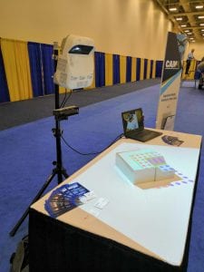
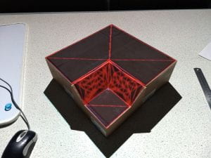
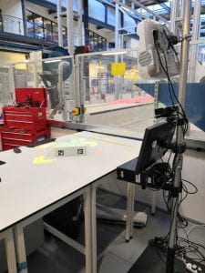
This series of posts is intended to showcase the top-level outcomes of Ufi Project 1 titled “Augmented Learning for High Dexterity Manufacture”. This project was funded by Ufi, a vocational learning charity. In this post we’ll be taking a look at how the whole system developed from it’s previous iterations. As mentioned in an earlier post there were two prior phases of what would eventually turn into the LayupRITE PIAR system.

The first stage was an early proof-of-concept of projecting interactive instructions onto the tool. The second stage was taking that concept and revising the individual elements, improving the projector, and using a newer version of Microsoft Kinect. The Ufi project allowed us to take these components and investigate ways of displaying/mounting them to produce what would become the LayupRITE PIAR system.
Physical Setup
In the left-hand image above, KAIL, the mounting solution was fairly ad-hoc, due to the short-term nature of the research project. The main downside being mounting the standard projector far away enough from the tool for the image to project over it. This necessitated the large fixturing stand shown in the above image which required sandbags to ensure it didn’t topple over, not an ideal setup for the longer-term.
The centre image is from a follow-on project intended to improve and “modernise” the KAIL system. The first difference is in using the updated version of the Kinect. The newer Kinect had a wider field of view and higher resolution depth and RGB cameras, as well as still being supported by Microsoft at the time. The other difference was that a higher-power, ultra-short throw projector was used in place of the standard long-throw version. This project was bright enough to show visible images on carbon fibre in normal clean room lighting conditions.

What was noted at this stage was that due to the short throw of the projector, steeper surfaces on parts would be in shadow. This meant that the projector had to be mounted further away from the tool, requiring new fixturing. The new mounting solution gave us the opportunity to mount other equipment, such as the PC and monitor to the pole along with the Kinect. This solution lowered the overall footprint and trailing cables and gave us the form factor for the LayupRITE PIAR system.
Software Setup
Most of the changes from KAIL to LayupRITE PIAR were in software. The previous iterations used the Windows Presentation Foundation (WPF) framework with C♯ as the scripting language. This limited the program to being 2D as the WPF is intended to make desktop apps on screens. The outlines of the instruction target sections were transformed manually by-eye to make the 2D lines conform to the tool. This meant that the software, as written at the start of the project would not work for a general case and needed changing.

What was required was a 3D environment that could better handle the collision detection and was compatible with the Kinect. For this we turned to the Unity game engine. Colleagues had had some experience of using Unity with the Kinect and VR in a related project to LayupRITE, so we felt we had enough of a basis to begin using it.
Moving to Unity
An enabling feature of the Unity platform is the “prefab”. Prefabs are building blocks of objects, scripts and other components which can be dropped into a “scene”, or program. These can then be updated in every scene or used as instances. What this means for this program is that we can drop in controls, virtual net objects, etc. This modularity can also enable us to swap out, for instance, the game “camera”, for PIAR this can be swapped to a projector-camera prefab, for another application it could be the HoloLens, or a VR headset. The ability to be modular was a major selling point for Unity for this project.

What Unity also allowed us to do was to make the hands tracked by the Kinect collide with the in-game representations of the composite net. The representations took the form of spheres (called “nodes” in the model) which represent the crossing points of fibres in a woven fabric. By tracking the interaction with these nodes, we can test and identify which areas of the tool have been interacted with by the user. This means that, through projection information on where to interact and when, we can guide the laminator into working in an optimal, or at least repeatable fashion.
The process for moving from the modelling environment to the projector environment followed a similar process to that of KAIL, but more streamlined:
- Simulate the drape of the ply
- Identify areas to work in and sequence (this is done by an experienced laminator)
- Select the nodes which represent those areas
- Project onto the part
Due to the 3D nature and calibrated camera-projector system no “nudging” of individual areas is required. All the above steps can be done in software, although there is still scope for streamlining and automating the steps.
Calibration and Tool Tracking
Calibration of this type (camera, projector stereo calibration) is large topic by itself, so here I’ll just mention that we were using the RoomAlive Toolkit for Unity. This is here the equivalent of KAIL’s “nudging” of the projected output came into play. Whilst the calibration was able to somewhat determine the intrinsic properties of the Kinect camera and the projector, its approximation of their relative positions and angles often required manual tweaking. This is most likely due to the relative angles of the Kinect and projector. A secondary parameter could also have been the ultra-short throw of the projector. Further work would be required to improve the overall quality of the calibration and make the process more streamlined.
A secondary feature which was implemented with limited success was in tracking the tool blocks. This meant that the tool could be moved or rotated, depending on either the user’s preference or to see projection data in shadowed areas. The OpenCV framework for Unity allowed us to use markers fixed to the tool to track its pose and location. The main issue with this was that it was difficult to determine if issues were caused by the tracking, the markers or the calibration.
Recording and Control
A goal of KAIL and this project was also to record and store what the laminator was doing, not just display instructions. To that end, since a camera was pointed at the laminator for the interactive functions, we could also record the laminators’ actions. Naturally, this recording process would be in the control of the operator. This recording of actions could in future be related to some capture of the ply outcomes and those to quality outcomes, from completed part ultrasonic scans. This data would enable us to construct a full model of how touch-level interactions can eventually lead to quality issues.

Controls were also to be provided by touch interaction. In a similar was to KAIL there were forward and back buttons to move through the layup stages. Additionally, there were buttons to control the recording, the image above shows the “pause” button on the right-hand side. These where projected buttons which were located on the table.
Second Screen
Another improvement from previous projects was the incorporation of a second screen. Since the application is run on a PC, adding another display (as well as the projector) was simple enough. Thus, the PC’s monitor was used to display additional information to the user. For this project it was intended more as a back-up to the projected info, but it also has the opportunity for displaying information such as where the part-in-progress will be going in a larger assembly/product. This line-of-sight to the final product is potentially a useful and important motivation factor.

