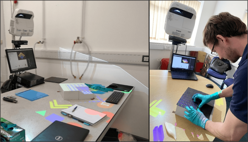
This series of posts is intended to showcase the top-level outcomes of Ufi Project 1 titled “Augmented Learning for High Dexterity Manufacture”. This project was funded by Ufi, a vocational learning charity. In this post we will be briefly looking over the outcomes of user trails. As part of the Ufi project trials were conducted with the NCC, two colleges and an SME. Since everyone outside of the NCC was volunteering their time, we sought to make the trials as unintrusive as possible, whilst still giving us useful information to work with.
Table 1: Total trial participants
Location Type Number College 31 NCC 23 SME 8 TOTAL 62
SME and College Trials
The SME and college trials were used to give us feedback on the “form and function” as well as suggest use cases for the system. It also enabled us to see how the system worked with example customers and get their thoughts. The system overall was generally well-received by students and laminators however, some did note the lengthy setup, and felt that the system needed further development.
In the college setting a key point of feedback was the unit cost. At the time of the trials the cost of the PC, projector and Kinect was somewhere in the region of £2000, the projector being the bulk of the cost. This did not include software. Some accommodations could be made, in that any Windows PC could possibly be used, although there are some compatibility issues with the Kinect and certain brands of USB cards. Another suggested solution was that one system be used with multiple users. This was certainly a possibility given that the Kinect has the capability to track and identify up to 6 users simultaneously.
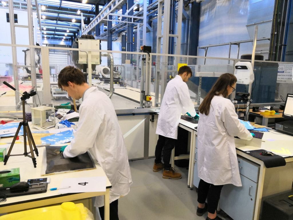
Trials with the National Composites Centre (NCC)
No Instructions
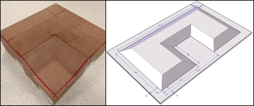
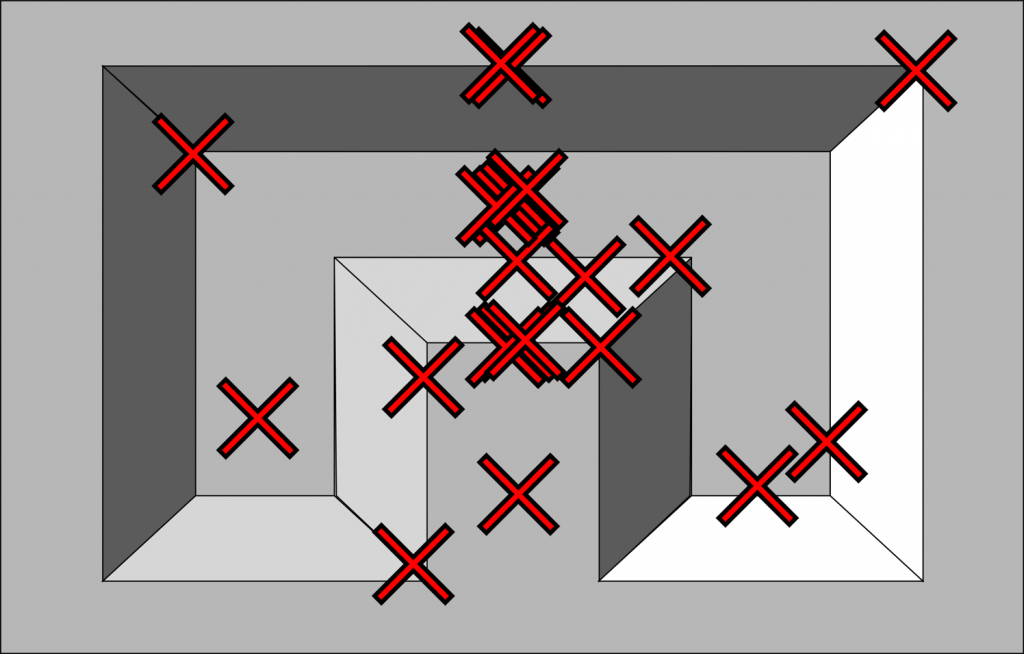
Laying-up the ply with no instructions gave us confirmation of a widely held belief in manual layup: everyone does it differently. Using video analysis, we determined the first point of pressure of the ply onto the tool, this would be the modelling equivalent of the seed point. There was a bias toward the middle of the component, or at least the centreline, which can be attributed to the part being symmetrical, however there is still a clear spread.
There was also one instance of a laminator cutting a ply on the tool to ensure proper fit. This is a relatively common occurrence with manual layup and the laminators were asked to use their best judgement about what to do to lay up the ply. Unfortunately in this case, the laminator actually caused damage to the tooling which might have effected the ability to de-mould the finished component.

These kinds of events could potentially go unrecorded under normal circumstances. Generally, the quality was somewhat mixed, due to time constraints and some material issues, so LayupRITE was unlikely to be the decisive factor in quality comparisons.
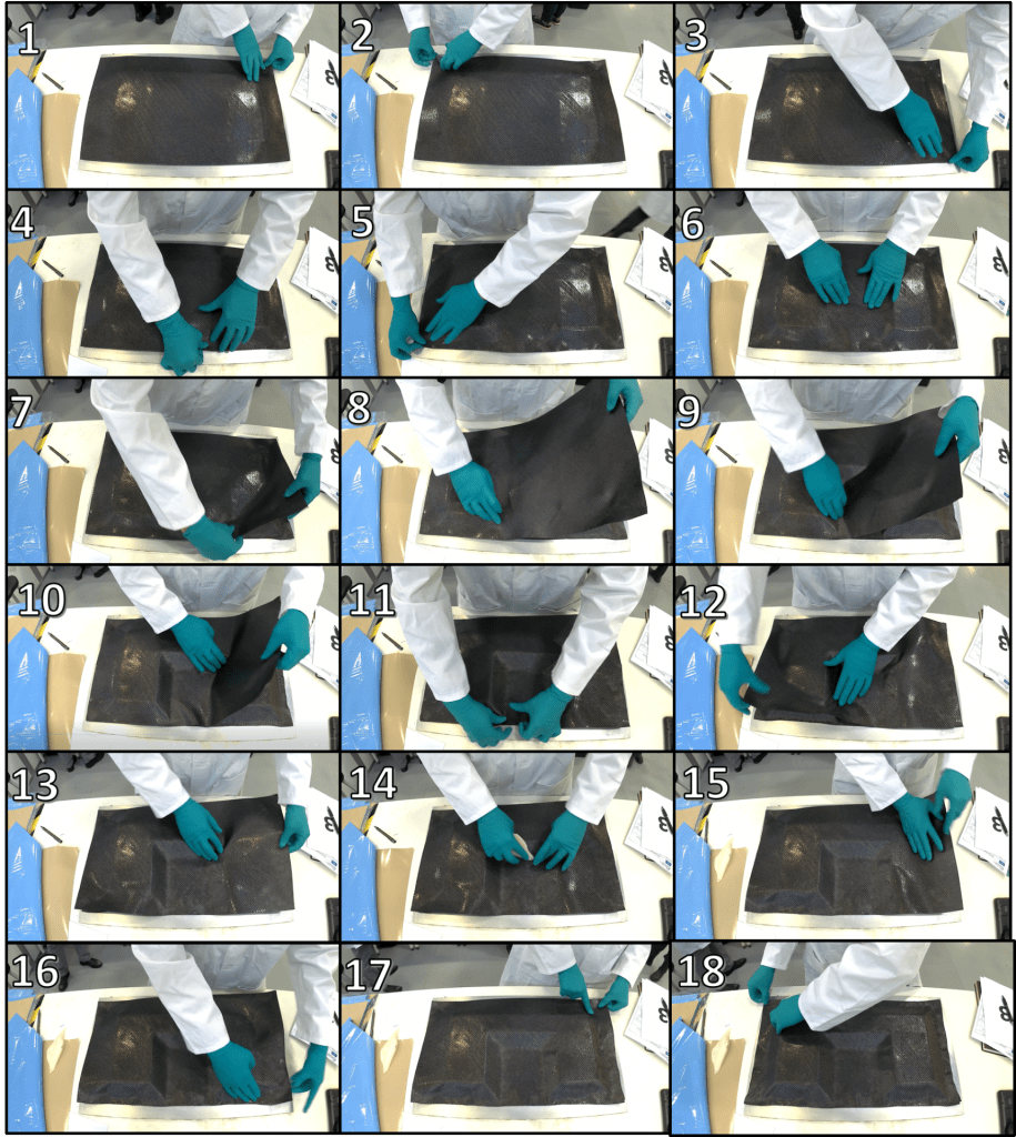
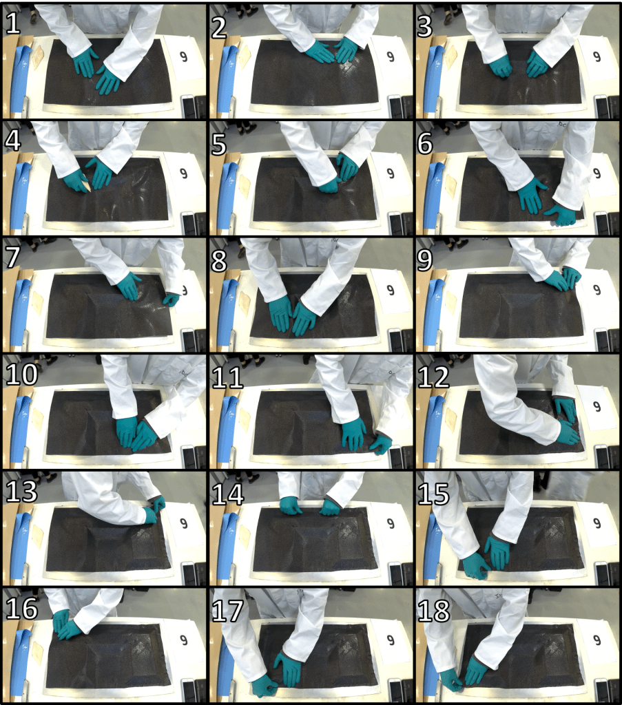
The sets of images above show the different routes laminators took to lay up the part. In addition to different starting points their processes were both different. In these selected examples, the laminators are both going back on themselves, rather than working out from the start point, as drape models would suggest is optimal.
Using LayupRITE
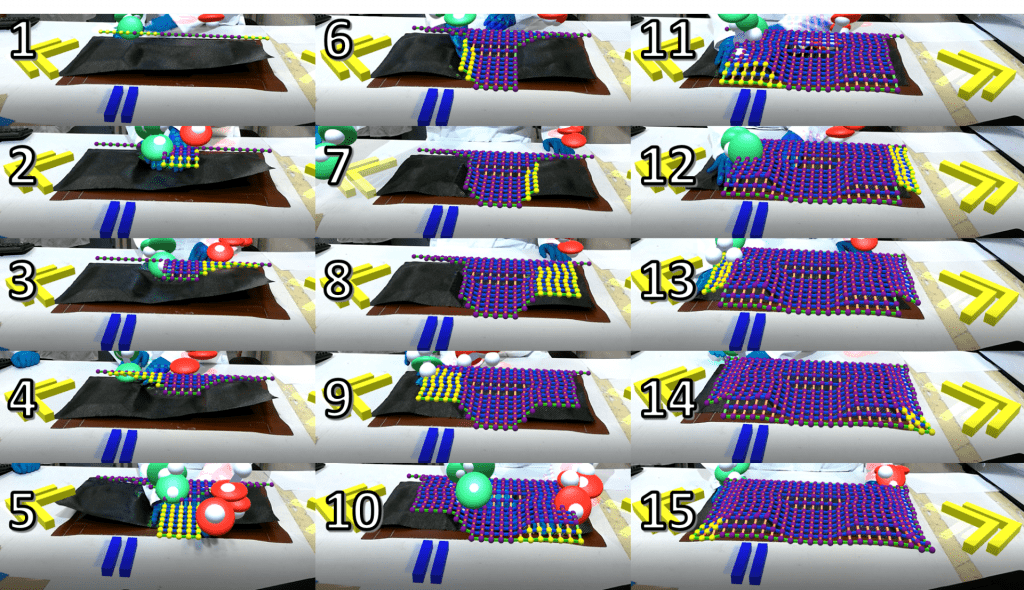
The LayupRITE instructions for this component were developed in a previous project with their aim being to symmetrically drape this component from a seed point. Since the next step in the process won’t appear until the current stage is complete, the participants all followed the projected instructions. This means that all the individual plies were laid-up using the same route. This route was not actively optimised but was intended to drive consistency. Additionally, by following the prescribed pattern, cutting the ply on the tool was not needed, so no “quality incidents” like the one mentioned above occurred.
Timing Results
Table 2: Comparison of time to lay down ply average and range
No Instructions Using LayupRITE % change Average 6m 30s 5m 53s -9.6 Range 7m 40s 6m 4s -20.9
The above table shows that using LayupRITE instructions reduced the average time to drape the ply over the U-shape tool. What is important to note is that it actually made the quickest laminator slower (a highly experienced technician), but that the average was reduced across all participants. The range of times was also reduced, this is important for planning out jobs since you know given the instructions roughly how long the steps will take.
Outcome of Trials
The trials showed us that the prototype system was useable but needed some further development before it could be a saleable product. Its main strengths were in that it was easy to understand and use, everyone “bought into” the idea. This is a key positive as it shows that we were along the right lines. The timing data showed that the system could be used to improve standardisation as well.
In terms of drawbacks the most obvious is in the setup requirements. The physical setup and calibration are both fairly lengthy processes but can be streamlined through further development. The physical setup can also be improved if a fixed, dedicated workstation is used. A secondary aspect which relates to the system was the cost for FE colleges. Whilst this wasn’t necessarily an issue for SMEs and larger companies, a branch off this system which is lower-cost would be useful to serve those potential customers.